Inverted V dipole calculation an construction .
Making your dipole antenna yourself is always better than buying one .
What do you need: cu wire ,
balun 1:1 and rope .
For the wire I use : CQ-532 antenna wire (AWG 18) , is a little more expensive but is UV resistant and
light weight .
The most widely used formula to calculate the approximate overall length of wire required for a
dipole is : 468 / frequency (MHz) = length of wire in feet or dipole length in meters :
143 / frequency in MHz .
Dipoles have a feed point of about 75 Ohm in free space and can be fed with a 50 Ohm to 75 Ohm
coax with or without a 1:1 balun .
The use of a balun is highly recommended .
By isolating the feedline, you won't get RF in the shack, and your dipole will behave like a real dipole .
Your coax line will be a coax line , not a part of your antenna .
Antenna wire velocity factor .
The standard 468/formula for cutting a dipole (and that the standard formula assumes a vf average of 0.95 ) .
To build a 80m (3,6 mhz) half-wave dipole , than the result is : 123,5ft (37,73m) of length .
Now we use in the formula the velocity factor and modify this to 0.98 :
((468/f) *vf) = (468/3,6) * .98) = 127,4ft .
((143/f) *vf) = (143/3,6) * .98) = 38,83m .
Or, if the velocity factor is 0.91 :
((468/f) *vf) = ((468/3,6) * .91) = 118,3ft .
((143/f) *vf) = ((143/3,6) * .91) = 36,14m .
Conclusion .
The velocity factor features (0.91, 0.95, and 0.98) mentioned in this thread are significant enough in difference to cause significant SWR and resonant frequency changes.
Special Calculation 3 % longer without velocity factor antenne wire .( Why , see below )
Interpreting the results .
The Half-Wave Dipole Antenna .
The length of wire required for a given frequency is found with the help of an antenna calculator . however, the actual resulting frequency of resonance and feed-point impedance of a dipole will depend on :
- The velocity factor of the antenna wire . ( CQ-532 wire has a velocity factor of about 0.96 - 0.98)
- The height of the dipole above ground .
- The conductivity of the ground below .
- The presence of buildings, trees, metal structures (tower) .
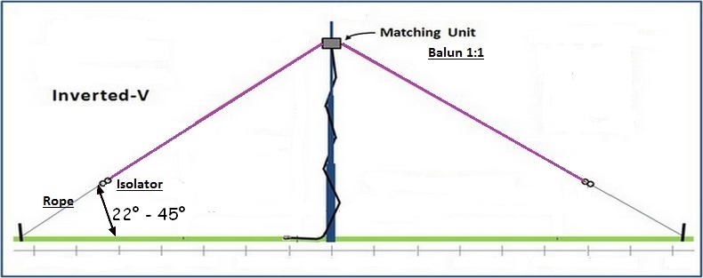
The Inverted V Dipole Antenna .
When each side of a dipole slopes down from the feed point , it is commonly called an inverted V and the results are different from a normal dipole .
- A more omni-directional radiation pattern than that of a normal dipole .
- A higher resonant frequency for the same length of wire as the dipole !!!!!!!!!!!!
- A lower feed point impedance than the horizontal dipole (for feed points at the same height above ground) .
- Some loss in Bandwidth .
Beware :
Some say that the inverted V should be cut 4-5% shorter than the dipole !
But if you do that, the inverted V would resonate at an even higher frequency !
Most calculators results for a inverted V antenna for 5.360 Mhz
Results : Each leg 13,04 Meter = resonate most of the time to high in frequency !!!!
Calculator I use here above .
Example : My calculation for a 5 Mhz dipole freq. 5.360 has a length of 13.43 meters each leg ,
Inverted V as 22 Degree . The antenna calculator above will give you a
wire length which will be 3% longer than that dipole at the desired frequency of
operation . This calculation will give you some leeway to trim the wire ends back .
As the two sections of the dipole are lowered below the feed point , the angle
between the two legs decreases with as results :
- The resonant frequency of the inverted V rises .
- The influence of the ground conductivity and dielectric constant becomes an increasing factor .
After installing the inveted V at 12M above ground I become for each leg : 13,4 Meter .
In my case , when I using the standard calculation formula its give my a big problem , the
standard calculation = 13,04 meter each leg , effect = 40cm to short !!
Note :
To avoid cutting the wire , I usually just fold back each end of the antenna wire
on itself and tape it tight if it's insulated wire - or twist it back on itself if you
are using bare wire . The resonance frequency shifts upwards .
After you can go easly back to the beginning of the band and vice versa .
Especially on the lower HF bands recommended , because the
bandwidth is not wide (100-150 Khz) . And for a temporary setup a must .
Therefore, the angle between the two legs of an inverted V should not be less than 90 degrees .
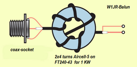
Balun 1:1 construction .
A lot of articles have been written about the meaning and the unintentional use of a
balun with a dipole antenna . My experience is: use a current balun.
Making a balun yourself is not difficult. The construction and choice of materials are important,
especially when using high power . On the picture you can see 2x4 turns , I using 2x6 turns .
Materials needed for a good home made current balun :
1: Ferrit Toroidring for instance FT240-61 or FT240- 43 or for lower bands FT240-31 .
2: 1 Meter Teflon coax cable like RG 142 or Rg 303 up to 2KW .
3: Waterproof plastic box .
4: PL SO239 socket .
5: M6 inox bolts and screws .
6: rubber sealing washers .
Winding technique is important ! With coax from outside to the ferrite ring. Wind 6 turns on one half of the ring, then through the ring to the other side and wind again 6 turns . The end of the winding should then be on the opposite position of the beginning of the winding. ( See picture ). Then, fix the winding with PVC tape .
A small hint for static discharge .
If the antenna has no connection to ground , add a small 10 K resistor between center conductor and braid of the coax to discharge static electricity .This prevents "noisy tick" from statics .
Navigation
ON7YK
- How I Started .
- on7yk/p
- Best Dx
- 6M DXCC
- Inverted V Calculation
- Loop Ant. Calculation
- RF sampler + dbm converstion
C5YK - C56YK - C5S
- Logbook

- C56YK Qth
- C56YK Dx Qsl Cards
- C5YK Qth till 2016
- C5YK Qth
- C5YK Dx Qsl Cards
- LoTW
- C5 - License
- ZD3 Op's till 1974
- C5 Op's 1975 till..
- E'Qsl
- 6M DXCC
- 6M EME setup
- 6M Beacons
- 6M Dx 2014
- 6M Dx 2015
Dx - Clusters
Links
Travelling
- Gambia Excursions
- Gambia Lodge
- Gambia Jan.2002
- Gambia Nov.2002
- Gambia Jan.2004
- Gambia Jan.2005
- Gambia Jan.2006
- Gambia Aug.2006
- Gambia 2014 +
- Austria Stubaital 2001
- Gambia-Belgium 2014
- North Cape 2014
- South-East Europe 2015
- Scandinavia 2016
- Scandinavia 2017
- North-East Europe 2018
- Baltic States 2019
- Sweden 2020
- Sweden 2021
- Sweden 2022
- Sweden 2023
- Scandinavia 2024